
CM1-630 AC MCCB Molded case circuit breaker
1.Application Area
CM1 series molded case circuit breaker are mainly applied to distribution system of 50HZ,rated insulation voltage 690V,rated current up to 1250A.It's purpose lays in power system distributing & protecting against malfunctions such as overload,short-circuit,undervoltage,etc.It also can be used as infrequent ON/OF switch under power system in normal conditioin.
Sorted by ultimate short-circuit breaking capacity,CM1 breakers can be defined as Model L(standards type),& Model M(high breaking capacity type).They're well-known for compact shape,high breaking capacity and short flashover distant,etc.
CM1 breakers can be either vertically or horizontally installed.
CM1 breakers comply to GB14048.2 standards,with CCC,CE approved.
2.Model Code
2.1 Model code indication
2.2 Sorted by application,there are distribution system type & motor protection type.
2.3 Sorted by operation,there are manual type,electtical operating type& rotatory handle type.
2.4 Sorted by wiring,there are front panel wiring type,back panel wiriing type & plugin ype.
2.5 Sorted by tripping unit,there are thermalmagent (duplex) type & eletromagnet(instantaneous) type.
Accessories can be further defined as inner accessories & external accessories,inner accessories include shunt trip,undervoltage trip,auxiliary contact&alarm contact,external accessories include rotatory handle,electrical operating module,etc.
3.Work Circumstance
3.1 Altitude of the installation place shall not be higher than 2000m(in case it's higher,do ask for advice from manufacturer first)
3.2 Circumstance temperature shouldn't ne higher than +40℃ or lower than -5℃,average temperature of 24h shouldn't exceed +35℃.
Attention:If temperature breaks the limits issued above,users shall operate the product according parameter shown in user manual or contat manufacturer for advice.
3.3 Working area shall not contain any explosive,metal corrosive or inductive media,the palce also should weatherproof.
3.4 Relative atmosphere humidity shall not exceed 50% when circumstance temperature is at 40℃,relative humidity could be higher if temperature drops,the average humidity of the most humid month shall not exceed 90%,in the meantime,average temperature of this month shall not be lower that +25℃,condensation on product surface due to temperature changing should be taken into consideration as well.
3.5 Pollution calss:3.Application type A.
4.Technical Data
4.1 Breaker's rated value & breaking capacity refers to Diagram 2
| Model | Structural rated current(A) | Rated current In(A) | Rated working voltage Ue(V) | Rated insulation voltage Ui(V) | Rated withstand voltage Uimp(KV) | Rated ultimate short-circuit breaking capacity Icu(kA) | Rated working short-circuit breaking capacity Ics(kA) | Phase | Flashover distance(mm) |
| CM1-63L | 63 | (6),10,16,20,25 32,40,50,63 |
400 | 690 | 6 | 35 | 18 | 3 | ≤50 |
| CM1-63M | 63 | 50 | 25 | ||||||
| CM1-100L | 100 | 16,20,25,32,40 50,63,80,100 |
400 | 690 | 6 | 35 | 18 | 3 | |
| CM1-100M | 100 | 50 | 25 | 3,4 | |||||
| CM1-225L | 225 | 100,125,160 180,200, 225 |
400 | 690 | 6 | 35 | 18 | 3 | |
| CM1-225M | 225 | 50 | 35 | 3,4 | |||||
| CM1-400L | 400 | 225,250,315 350,400 |
400 | 690 | 6 | 50 | 35 | 3 | |
| CM1-400M | 400 | 65 | 42 | 3,4 | |||||
| CM1-630L | 630 | 400,500 630 |
400 | 690 | 6 | 50 | 35 | 3,4 | |
| CM1-630M | 630 | 65 | 42 | ||||||
| CM1-800L | 800 | 630,700 800 |
400 | 690 | 6 | 50 | 35 | 3,4 | ≤100 |
| CM1-800M | 800 | 75 | 37.5 | ||||||
| CM1-1250M | 1250 | 80,010 001,250 |
400 | 690 | 6 | 80 | 42.5 | 3 |
Attention:6A break doesn't have thermalmagnet trip
100L,M & 225L,M can equip cage type (lift type) terminals.
4.2Distribution system breaker's instantaneous acting feature is 10In±20%,motor protection breaker's instantaneous acting feature is 12In±20%.Breaker's overcurrent protecting features refer to Diagram 3&4.
Diagram 3 distribution system breaker overcurrent features
| Serial No. | Testing current (times) | Tripping time | Status | Circumstance temperature |
| 1 | 1.05In | 1h non-tripping (In≤63A),2h non-tripping(In>63A) | Initial | +40℃±2℃ |
| 2 | 1.3In | 1h tripping (In≤63A),2h non-tripping(In>63A) | Following Serial 1 | |
| 3 | 10In | ≤0.2s tripping | Initial | Any suitable temperature |
Diagram 4 motor protection breaker overcurrent features
| Serial No. | Testing current (times) | Tripping time | Status | Circumstance temperature |
| 1 | 1.05In | 2h non-tripping | Initial | +40℃±2℃ |
| 2 | 1.3In | 2h tripping | Following Serial 1 | |
| 3 | 10In | ≤0.2s tripping | Initial | Any suitable temperature |
5.Shap & Dimension
5.1 CM1-63,100,225 front panel connecting shape & dimension
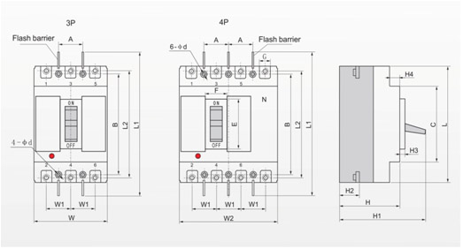
| Dimension type | Dimension code | Model | |||||
| CM1-63L | CM1-63M | CM1-100L | CM1-100M | CM1-225L | CM1-225M | ||
| Product dimension | C | 85 | 85 | 84 | 84 | 102 | 102 |
| E | 48 | 48 | 50.5 | 50.5 | 50 | 50 | |
| F | 22 | 22 | 22 | 22 | 22 | 22 | |
| G | 14 | 14 | 17.5 | 17.5 | 23 | 23 | |
| H | 72 | 82 | 68 | 86 | 86 | 103 | |
| H1 | 90 | 100 | 86 | 104 | 110 | 127 | |
| H2 | 18 | 28 | 24 | 24 | 24 | 24 | |
| H3 | 4 | 4 | 4 | 4 | 4 | 4 | |
| H4 | 6 | 6 | 7 | 7 | 5 | 5 | |
| L | 135 | 135 | 150 | 150 | 165 | 165 | |
| L1 | 235 | 235 | 255 | 255 | 360 | 360 | |
| L2 | 117 | 117 | 136 | 136 | 144 | 144 | |
| W | 76 | 76 | 90 | 90 | 105 | 105 | |
| W1 | 25 | 25 | 30 | 30 | 35 | 35 | |
| W2 | - | 105.5 | - | 120 | - | 140 | |
| Install dimension | A | 25 | 25 | 30 | 30 | 35 | 35 |
| B | 117 | 117 | 129 | 129 | 126 | 126 | |
| φd | 4.5 | 4.5 | 4.5 | 4.5 | 5 | 5 | |
5.2 CM1-400,630,800,1250 front panel connecting shape & dimension
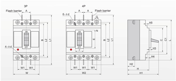
| Dimension type | Dimension code | Model | ||||||
| CM1-400L CM1-400M 3P |
CM1-400L CM1-400M 4P |
CM1-630L CM1-630M 3P |
CM1-630L CM1-630M 4P |
CM1-800L CM1-800M 3P |
CM1-800L CM1-800M 4P |
CM1-1250M 3P |
||
| Product dimension | C | 127.5 | 127.5 | 134 | 134.5 | 136 | 136 | 265.5 |
| C1 | 173.5 | 173.5 | 184.5 | 184.5 | 204 | 204 | 345.5 | |
| E | 88.5 | 88.5 | 89 | 89 | 81 | 81 | 97 | |
| F | 65 | 65 | 65.5 | 65 | 66 | 66 | 78 | |
| G | 30.5 | 30.5 | 44 | 44 | 45 | 45 | - | |
| H | 107 | 107 | 112 | 112 | 116 | 116 | 141 | |
| H1 | 162 | 162 | 164.5 | 164.5 | 168 | 168 | 202 | |
| H2 | 38 | 40 | 41.5 | 42 | 41.5 | 41.5 | 58 | |
| H3 | 6.5 | 6 | 7 | 6.5 | 4.5 | 4.5 | 16.5 | |
| H4 | 5.5 | 5 | 3.5 | 3.5 | 5 | 5 | 2 | |
| H5 | 5 | 4.5 | 4.5 | 4.5 | 8 | 8 | 4.5 | |
| L | 257 | 257 | 270.5 | 270.5 | 280 | 280 | 406 | |
| L1 | 457 | 457 | 470 | 470 | 470 | 485 | 715 | |
| L2 | 224 | 224 | 234 | 234 | 243 | 243 | - | |
| W | 150 | - | 182 | - | 210 | - | 210 | |
| W1 | 48 | 48 | 58 | 58 | 70 | 70 | 70 | |
| W2 | - | 197.5 | - | 240 | - | 280 | - | |
| Install dimension | A | 44 | 44 | 58 | 58 | 70 | 70 | 70 |
| B | 194 | 194 | 200 | 200 | 243 | 243 | 375 | |
| φd | 7 | 7 | 7 | 7 | 7 | 7 | 10 | |
