
C45L-63 Residual current circuit breaker 2 Pole
1.General
1.1 Application
Personnel and fire protection
Cable and line protection against overload and short circuits
1.2 General rules for choosing RCBO:
a.Rated residual operating current
I△n≤30 mA:additional protection in the case of direct contact
I△n≤300 mA:preventative fire protection in the case of ground fault currents
b.Tripping class
AC class - Tripping is ensured for sinusoidal,alternating currents,whether they be quickly applied or slowly increase.
A class - Tripping is ensured for sinusoidal,alternating residual currents as well as for pulsed DC residual currents,whether they be quickly applied or slowly increase.
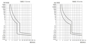
c.Tripping curve
C curve (5-10 In) protection and control of the circuits against overloads and short-circuits;protection for resistive and inductive loads with low inrush current.
D curve (10-14 In) protection and control of the circuits against overloads and short-circuits;protection for resistive which supply loads with high inrush current at the circuit closing(LV/LV transformers,breakdown lamps).
2. Technical Data
2.1 Curves
| Standard | IEC/EN 61009-1 | ||
| Electrical features | Type(wave form of the earth leakage sensed) | AC | |
| Thermo-magnetic release characteristic | C,D | ||
| Rated current In | A | 6,10,16,20,25,32,40,50,63 | |
| Rated voltage Ue | V | 230/400 | |
| Rated sensitivity I△n | A | 0.03,0.1,0.3 | |
| Rated residual making and breaking capacity I△m | A | 500 | |
| Rated short-circuit capacity Icn | A | 4,500/6,000 | |
| Break time under I△n Rated frequency | S | ≤0.1 | |
| Hz | 50/60 | ||
| Rated impulse withstand voltage (1.2/50)Uimp | V | 4000 | |
| Dielectric test voltage at ind.Freq.for 1 min | kV | 2 | |
| Insulation voltage Ui | 500 | ||
| Pollution degree | 2 | ||
| Mechanical features | Electrical life | 2000 | |
| Mechanical life | 2000 | ||
| Contact position indicator | Yes | ||
| Protection degree | IP20 | ||
| Ambient temperature (with dally average≤35℃) | ℃ | -5...+40(Special application please refer to P65 for temperature compensation correction) | |
| Storge temperature | ℃ | -25...+70 | |
| Installation | Terminal connection type | Cable/U-type busbar/Pin-type busbar | |
| Terminal size top/bottom for cable | mm2 | 25 | |
| AWG | 18-3 | ||
| Terminal size top/bottom for busbar | mm2 | 25 | |
| AWG | 18-3 | ||
| Tightening torque | N*m | 2 | |
| In-Ibs. | 18 | ||
| Mounting | On DIN rail EN 60715 (35mm) by means of fast clip device | ||
| Connection | From top and bottom (for combined type) | ||
| From top (MCB+add-on RCB block) | |||
2.3 Temperature derating
| Temperature | -15℃ | -5℃ | 0℃ | 10℃ | 20℃ | 30℃ | 40℃ | 55℃ |
| Temperature compensation coefficient of rated current | 1.19 | 1.15 | 1.13 | 1.06 | 1.05 | 1 | 0.96 | 0.89 |
3. Overall and Mounting Dimensions(mm)
3.1 MCB+add-on RCD block
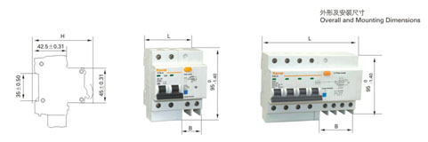
| Number of poles | In=6~32A | In=40~63A | ||||
| L(mm) | H(mm) | B(mm) | L(mm) | H(mm) | B(mm) | |
| 1P+N | 45 | 74 | 27 | 54 | 74 | 36 |
| 2P | 63 | 77.8 | 27 | 72 | 77.8 | 36 |
| 3P | 90 | 77.8 | 36 | 103.5 | 77.8 | 49.5 |
| 3P+N | 99 | 77.8 | 45 | 117 | 77.8 | 63 |
| 4P | 117 | 77.8 | 45 | 135 | 77.8 | 63 |
