GV2 Motor Protection Circuit Breaker with auxiliary
Application Area
GV2 series moulded case circuit breaker mainly applies to power systems of AC 690V,50HZ,rated current ranged from 0.1~32A,its purpose lays in protection against overload,phase defect,short-circuit,etc.under 3-phase rotor cage induction motor system,it also can work as infrequent ON/OFF switch and isolator.
GV2 approves CCC,CE,TSE certificate.
Working Circumstance
2.1 Altitude of the install place shall not be higher than 2000m.
2.2 Circumstance temperature shouldn't be higher than +40℃,or lower than -5℃.
2.3 Relative humidity shall not be higher than 50% when temperature at the highest +40℃.
Averange humidity of the most humid month shall not exceed 90%,while average temperature of this month shall not be lower than 20℃.
2.4 Pollution class:3
2.5 Install type:Ⅱ,Ⅲ(load class & distributing class)
2.6 Inclination between install plane surface and vertical plane surface shall not exceed ±5°.
2.7 Working system:uninterrupted type.
Working Theory & Structure Characteristics
GV2 circuit breaker is an integrated equipment which includes the functions of isolator,breakers,thermal relay,etc.It can effectively protect power system from malfunctions as overlaod,phase defect,temperature compensation,short-circuit,etc.
GV2 circuit breaker complies to GB14048.2,GB14048.4,IEC40947-2,IEC60947-4-1 standards.
GV2 structure:connected to mian circuit through thermal components,while motor suffers from overload,the bimetallic strip inside got heated up to trigger the circuit breaker to break off.
When motor suffers from phase defect,the bimetallic strip of this phase would cool down and recover its shape,by differential device's enlarging effect,circuit break would break off.While current reach the limit of instantaneous electromagnetic trip,magnetic core acts at once,forcing lever to cut off the current while driving operating module to trip,making circuit breaker to break off.
GV2 breaker is in consist of bottom foundation,contact support,arc-chute,insulating base,thermal-magnetic system(including instantaneous electromagnetic tripping unit,bimetallic strip,thermal components,etc.),differential device,curent adjusting device,operating module,product cover,push button and so on.
GV2 breaker adopts flip-over direct-acting type double contacts structure,contact bridge,contact support & arc-chute are installed in the bottom foundation,thermal-magnetic system,static contact,operating module,differential device,current adjusting device are iinstalled on base.There is a breaking test function,toggle the handle inside the "test" column according to the printed arrow to make sure the overload tripping function is reliable.
Technical Data
4.1 Rated insulation voltage Ui(V):690
4.2 Rated impulse withstanding voltage Uimp(kV):6
4.3 Rated working voltage Ue(V):230(240),400(415),440,500,690
4.4 Rated frequency (Hz):50
4.5 Structural level rated current Inm(A):32
4.6 Rated current In(A):refer to Diagram 1
4.7 Rated breaker operating lifespan:refer to Diagram 2
4.8 Breaker's overcurrent protection features:refer to Diagram 3,Diagram 4.
Diagram 1 Breaker's specification & short-circuit breaking capacity.
| Serial No. | Trip rated current In(A) |
Thermal components current adjustable range(A) |
Rated ultimate short-circuit breaking capacity(Icu) Rated working short-circuit breaking capacity(Ics) |
||||||||||
| 230/240V | 400/415V | 440V | 500V | 690V | Arc distance | ||||||||
| Icu(kA) | Ics(kA) | Icu(kA) | Ics(kA) | Icu(kA) | Ics(kA) | Icu(kA) | Ics(kA) | Icu(kA) | Ics(kA) | ||||
| 1 | 0.16 | 0.1-0.16 | 100 | 100 | 100 | 100 | 100 | 100 | 100 | 100 | 100 | 100 | 50mm |
| 2 | 0.25 | 0.16-0.25 | 100 | 100 | 100 | 100 | 100 | 100 | 100 | 100 | 100 | 100 | |
| 3 | 0.4 | 0.25-0.4 | 100 | 100 | 100 | 100 | 100 | 100 | 100 | 100 | 100 | 100 | |
| 4 | 0.63 | 0.4-0.63 | 100 | 100 | 100 | 100 | 100 | 100 | 100 | 100 | 100 | 100 | |
| 5 | 1 | 0.63-1 | 100 | 100 | 100 | 100 | 100 | 100 | 100 | 100 | 100 | 100 | |
| 6 | 1.6 | 1-1.6 | 100 | 100 | 100 | 100 | 100 | 100 | 100 | 100 | 100 | 100 | |
| 7 | 2.5 | 1.6-2.5 | 100 | 100 | 100 | 100 | 100 | 100 | 100 | 100 | 3 | 2 | |
| 8 | 4 | 2.5-4 | 100 | 100 | 100 | 100 | 100 | 100 | 100 | 100 | 3 | 2 | |
| 9 | 6.3 | 4-6.3 | 100 | 100 | 100 | 100 | 50 | 50 | 50 | 50 | 3 | 2 | |
| 10 | 10 | 6.0-10.0 | 100 | 100 | 100 | 100 | 15 | 10 | 10 | 10 | 3 | 2 | |
| 11 | 14 | 9.0-14.0 | 100 | 100 | 6 | 2 | 6 | 2 | 6 | 2 | 3 | 2 | |
| 12 | 18 | 13.0-18.0 | 100 | 100 | 6 | 2 | 6 | 2 | 6 | 2 | 3 | 2 | |
| 13 | 23 | 17.0-23.0 | 50 | 50 | 6 | 2 | 6 | 2 | 6 | 2 | 3 | 2 | |
| 14 | 25 | 20.0-25.0 | 50 | 50 | 6 | 2 | 6 | 2 | 6 | 2 | 3 | 2 | |
| 15 | 32 | 24.0-32.0 | 50 | 50 | 6 | 2 | 6 | 2 | 6 | 2 | 3 | 2 | |
Diagram 2 Breaker's operating lifespan
| 1 | 2 | 3 | 4 | 5 | |||||
| Structural level rated current Inm(A) | Operating times per hour | Operating times | |||||||
| Electrical | Mechanical | Total | |||||||
| 25 | 120 | 2000 | 20000 | 22000 | |||||
Diagram 3 Distribution system breaker's features while each phase under balanced load
| Serial No. | Testing current | Acting time | Status | Circumstance temperature |
| 1 | 1.05In | 1h non-tripping | Initial | +40℃±2℃ |
| 2 | 1.3In | 1h tripping | Following serial 1 | |
| 3 | 10In | ≤0.2s tripping | Initial | Any suitable temperature |
Diagram 4 Motor protection breaker's features while each phase under balanced load
| Serial No. | Testing current | Acting time | Status | Circumstance temperature |
| 1 | 1.05In | 2h non-tripping | Initial | +40℃±2℃ |
| 2 | 1.2In | 2h tripping | Following serial 1 | |
| 3 | 1.5In | 3min tripping | Connect to serial 1 current till breaker reaches thermal balance | |
| 4 | 7.2In | 2~10s tripping | Initial | |
| 5 | 12In | ≤0.2s tripping | Initial | Any suitable temperature |
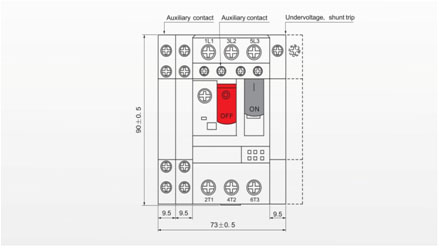
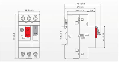
Shape & Dimension
Accessory
6.1 Breaker can be equipped with undervoltage trip,shunt trip (shunt & undervoltage can't be equipped simultaneously.),auxiliary contact,etc,When voltage drops to 35%~70% of rated voltage,undervoltage trip shall act,voltage becomes lower than 35% of rated voltage,undervoltage trip would prevent breaker from switching on,voltage become higher than 85% of rated voltage,undervoltage trip shall secure that the braker switches on.
6.2 Shunt trip features
Shunt trip's trigger voltage is 70%~110% of rated voltage,thus effectively making the breaker switches off.
6.3 Accessory install position & dimension refer to below picture.